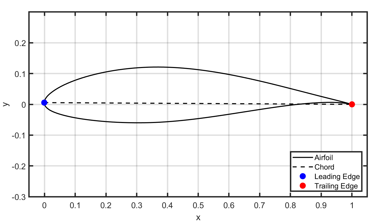
This project presents a model of the NACA 63(3)-618 airfoil at various Reynolds Numbers and with varying angles of attack (alpha). The figure below shows the NACA 63(3)-618 airfoil to be analyzed.
Airfoil properties can be modeled through the use of the XFoil development system. This process can be automated by creating a MATLAB script that sends a text file of commands to XFoil and stores the output as variables. First, the lift coefficient (CL) is found for angles of attack between -10 and 20 degrees at three Reynolds Numbers (3 million, 10 million, and 15 million).
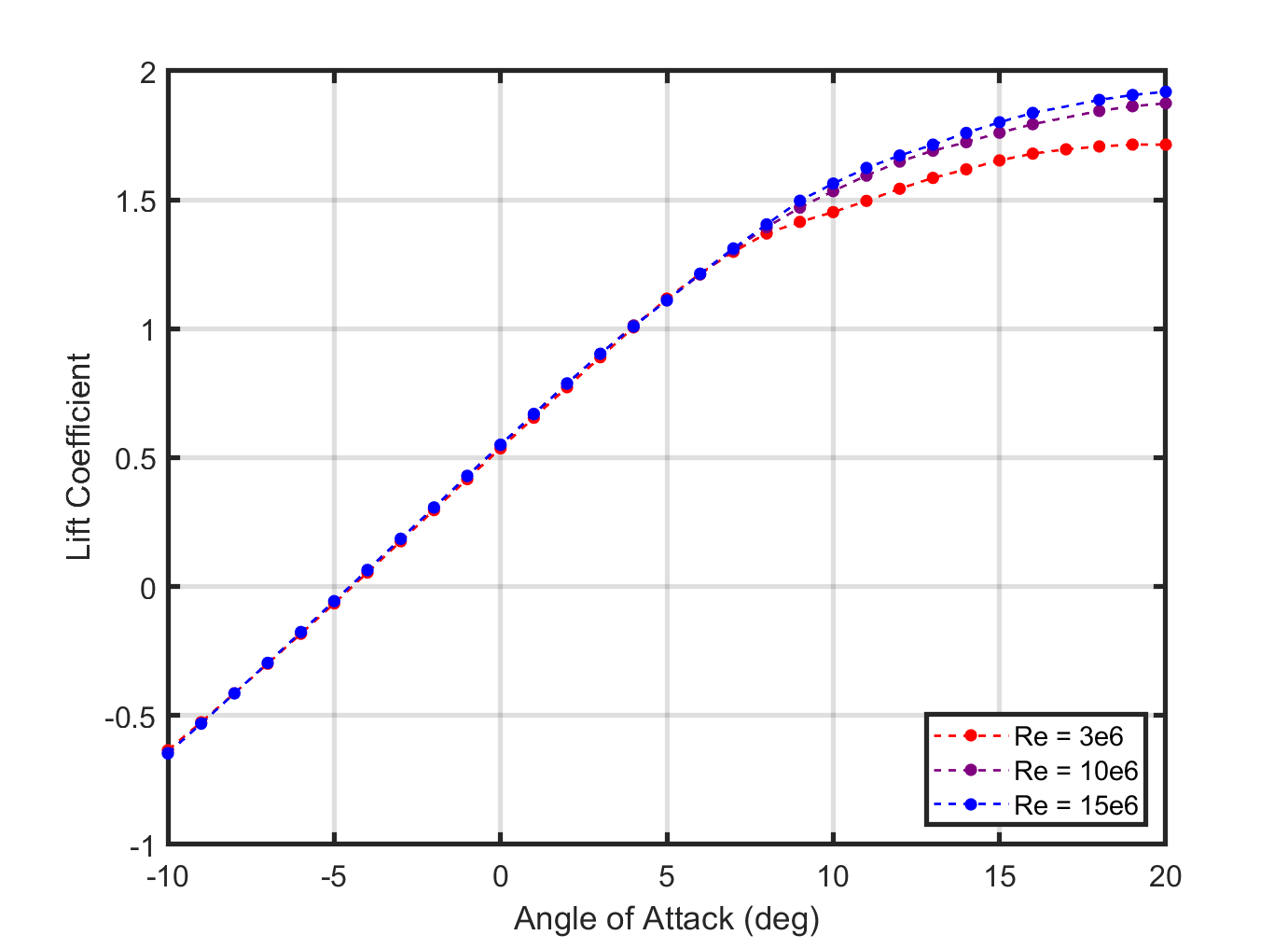
As can be seen, there is similar lift for all Reynolds numbers. Additionally, there is linear growth in CL from -10 degrees to around 7 degrees. After this point, there is diminished returns in increasing alpha. The drag coefficient (CD) is also found for the same alpha range and Reynolds Numbers. The results are shown in the figure below.
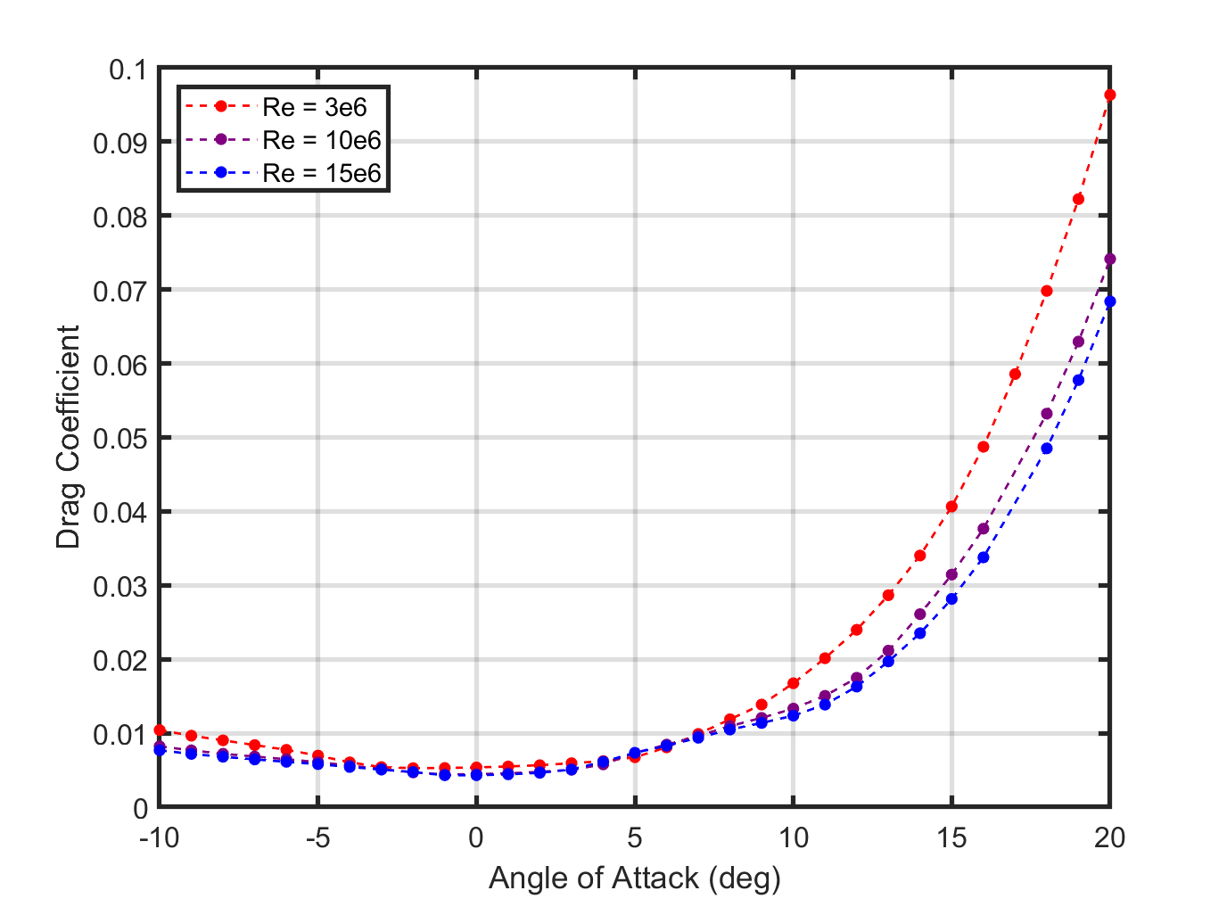
The downsides in increasing become more clear when analyzing drag. At approximately 10 degrees, a significant increase in drag is seen. This is counterproductive to wind turbine design, as this drag adds significant load to the blades. Again, similar drag is experienced at all Reynolds Numbers. In this way, it is desirable to maximize the ratio of the lift coefficient over the drag coefficient, also known as the lift to drag ratio. It is expected that a high lift to drag ratio will be evident at the values resulting in the smallest CD and the largest CL. The pitching moment coefficient (CM) is another important characteristic of an airfoil. A pitching moment with high magnitude indicates increased torque on the pitch axis of the blade.
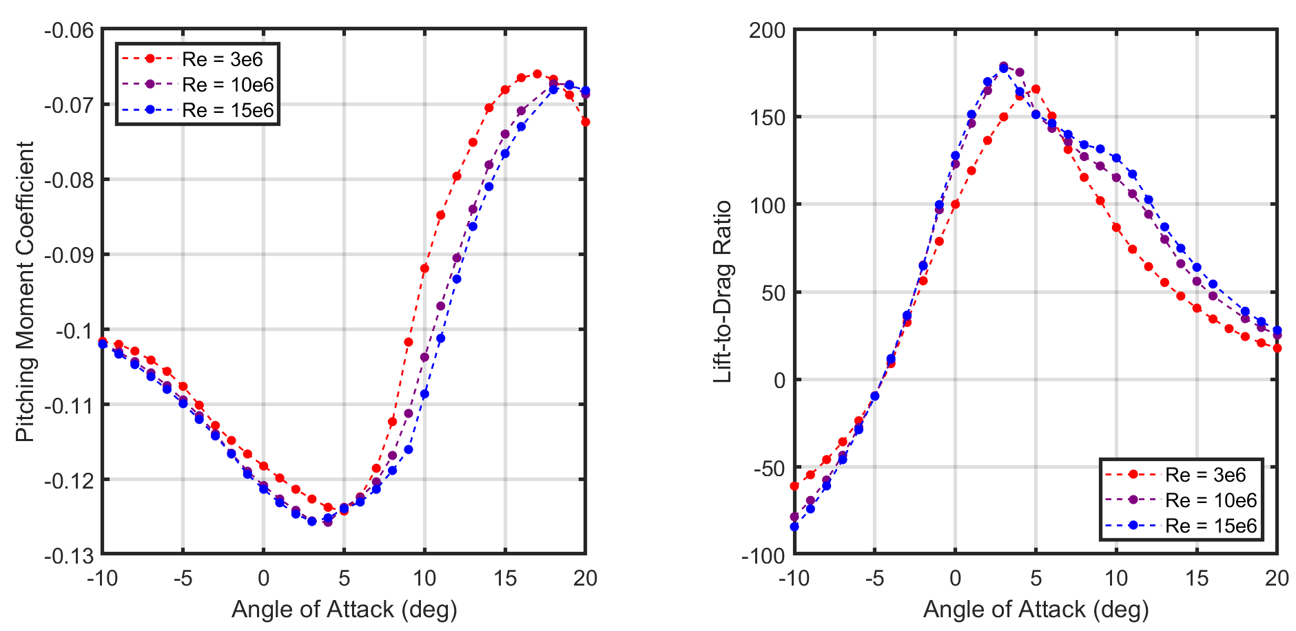
In this case, the pitching moment is negative which indicates the torque on the pitch axis is in the nose down direction. To maximize the lift to drag ratio, the blade structure must be strong enough to handle the increased torque on the pitch axis. Another important characteristic of wind turbine blade design is the pressure experienced along the edge of the airfoil. This can be modeled with an additional dimensionless metric, the pressure coefficient (CP).

Lastly, boundary layer properties were analyzed at the trailing edge of the airfoil. This provides useful insight to the condition of airflow after passing by the wind turbines blades. In this way, the boundary layer properties provide insight to the wake of the wind turbine. The displacement thickness quantifies the mass of airflow lost with the boundary layer condition. The momentum thickness quantifies the momentum of airflow lost with the boundary layer condition. The ratio of these two measurements can be utilized to draw further conclusions. This value is known as the shape factor (H). A smaller shape factor is commonly associated with more turbulent flows.

The shape factor reaches a minimum at around 8 degrees. This suggests that the most turbulent flow at the trailing edge occurs with an angle of attack of 8 degrees. Given the above results, recommendations for the operating value can be made. For the purposes of this project, angles of attack will be chosen to maximize the lift to drag ratio While L/D is maximized, this solution comes at a cost. The pitching moment at this has the largest magnitude in the range analyzed. This will result in a nose-down moment, simultaneously decreasing alpha and introducing strain. For longevity, a slightly shallower angle of attack is recommended (0 degrees). At this angle, the drag is still minimal and the lift to drag ratio is
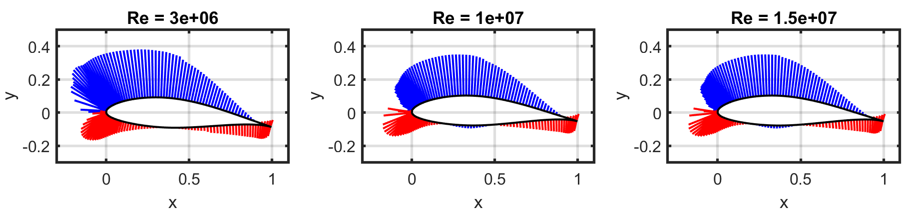
over 100. Next, the pressure distributions were found at these angles. To better visualize CP relative to the airfoil, vectors are plotted in Figure 7 on the airfoil topology with magnitude proportional to the magnitude of CP at that respective point. Negative CP is shown in blue and positive CP is shown in red.
over 100. Next, the pressure distributions were found at these angles. To better visualize CP relative to the airfoil, vectors are plotted in Figure 7 on the airfoil topology with magnitude proportional to the magnitude of CP at that respective point. Negative CP is shown in blue and positive CP is shown in red.
In conclusion, an angle of attack of 3-5 degrees optimizes wind turbine potential for Reynolds Numbers between 3 million and 15 million. Yet, this configuration presents potential issues. First, this alpha results in a large pitching moment coefficient. This torque along the pitch axis can be decreased with a more shallow alpha (around 0 degrees). Additionally, there is a high pressure concentration near the trailing edge. Changing the angle of attack, however, will not have a substantial effect on the pressure at this point. This problem must be resolved structurally. Next, this orientation may not be optimal for wind farms. To limit the turbulence in the wake of individual wind turbines, an angle of attack of around -3 degrees is recommended.